0 Introduction
Slurry treatment equipmentIn recent years, it has been used in the construction of subways and real estate in large and medium-sized cities, and the mud generated during the construction will pollute the cityscape, basic agricultural land and underground water. Construction mud is mainly produced by the following types of projects: drilled pile construction mud is produced by rotary drilling rigs, forward and reverse cycle drilling rigs, percussion drilling rigs and other drilling methods; underground continuous wall construction mud is produced by continuous wall, double-wheeled milling and other equipment to form a trench; mud and water shield construction mud is produced by the mud and water balanced shield tunnel construction; non-excavation construction mud is produced by horizontal directional drilling and mud and water pipe jacking construction. Construction mud consists of liquid and clay, supplemented by additives, and is mainly used to protect the hole wall and carry the drill cuttings out of the hole. In the process of drilling, due to the drilling slag constantly entering into the mud, the specific gravity, viscosity and sand content of the mud change, and cannot meet the requirements of mud performance, it must be purified, that is, the solid-liquid separation and then the drilling slag in the mud is separated and circulated for use. At present, a large amount of waste mud is generated during and after the operation cycle of diaphragm wall and pile foundation construction. The waste mud contains clay minerals such as montmorillonite and rock debris, and its consistency is so large that it can neither be discharged directly, nor can it settle naturally within a short period of time. If not treated in time, it will not only affect the construction, but also cause environmental pollution or water pollution and other secondary public hazards, such as the waste slurry is difficult to degrade in the natural state, which will cause soil crusting in the surrounding areas, salinisation of the soil, and massive destruction of vegetation; the waste slurry accumulates and infiltrates into the sub-surface layer of the groundwater for a long period of time, or flows into the rivers and creeks along with the spillage of rainwater, which will pollute the water sources and endanger the people's health; and the waste slurry piles up in the vicinity of the construction site, which will occupy large amounts of cultivated land or grassland. Waste slurry piled up around the construction site occupies a large amount of arable land or grassland, so that the occupied land loses its use value and becomes a new source of pollution. At present, there are more and more researches on waste slurry treatment in China, and the main treatment methods include chemical solidification treatment method, land cultivation treatment method, solid-liquid separation treatment method, etc. Among them, the solid-liquid separation treatment method is the most suitable method for the treatment of waste slurry. Among them, the solid-liquid separation method is relatively simple, the produced water can be discharged directly, and the discharged dry mud can be landfilled, which is especially suitable for the treatment of drilling mud in municipal underground projects. This paper gives an overview of domestic solid-liquid separation mud treatment equipment on the basis of extensive research, and designs a new type of mobile mud treatment equipment.
1 common domestic slurry treatment equipment
At present, the main mechanical equipment used to treat slurry by solid-liquid separation methods include vibrating screens, cyclone slurry purifiers and horizontal screw centrifuges.
1.1 Vibrating screens use high-frequency vibration to separate the solid particles in the slurry flowing through the screen cloth. Vibrating screen cloth is available in a variety of mesh sizes, with 100 mesh (separating particles with a diameter of 0.15 mm or larger) or coarser cloth generally used, and 200 mesh being the densest cloth used. Vibrating screens are generally located at the front end of the process and are mainly used to treat large solid phases.
1.2 Cyclone slurry purifier After pumping the slurry into the cyclone, the slurry will be restricted by the shape of the cyclone and produce high speed cyclone. Under the action of centrifugal force, the solid phase with higher density than the liquid will be leaning against the wall of the cylinder, while the liquid with lower density will be in the middle of the cylinder, so that the coarser particles will be separated out from the slurry. Cyclone mud purifier solves the problem of recycling mud on site, improves the efficiency of mud recycling, and saves cost, but it does not solve the problem of disposal of waste mud.
1.3 Horizontal screw centrifuge is the only solid-liquid separation device that can remove the free liquid on the surface of solid-phase particles. The larger the rotational speed of the centrifuge, the smaller the particle size of the solid phase particles that can be separated, and when the rotational speed of the centrifuge reaches 3200 r-min-1, the smallest particle size that can be separated is 2 μm. The centrifuge is generally located at the end of the treatment process, and it is mainly used to treat small particles of solid phase. According to the particle size and particle size grading of the solid phase substances in the slurry, and considering the performance requirements of the treated slurry, different treatment processes can be selected, but the order of treating the large particles first and the small particles second must be followed. Since the working principle of horizontal screw centrifuge is to separate solid and liquid by using the centrifugal force generated by mass difference, it is necessary to pre-treat the slurry, that is to say, to add flocculants to destroy the colloidal structure of the slurry and form the mass difference between the inner substances. Since there are many kinds of flocculants (anion, cation, organic flocculants, etc.), each of which has different effects on the soil, and the price of flocculants is high, generally RMB 20,000 yuan per tonne, and the quantity of pre-treatment is also large, about 5kg-m-3; therefore, the cost of using horizontal centrifuge is high, which is not conducive to the promotion of it.
2 Design of new mobile slurry treatment equipment
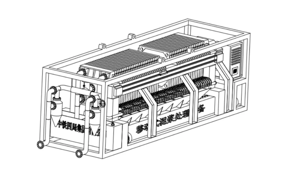
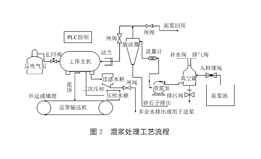
2.1 Design Principle The main structural parts of this equipment include screen filter head, slurry pump, vacuum tank, valve, hydraulic cyclone, diaphragm filter press, press system, backblowing system, automatic pulling plate system, belt machine. The specific work flow is as follows: firstly, the vacuum tank is filled with clean water, and the operator turns on the slurry pump start button, and the lead water in the vacuum tank is pumped out, which makes the vacuum tank generate negative pressure, and the slurry in the slurry tank is automatically sucked into the vacuum tank when the pressure is large enough to achieve continuous self-absorption of the slurry; when there is a need to recycle the slurry, the inlet to the valve of the hydraulic cyclone is turned on and the solid particles of the slurry, such as gravel with a large particle size, are filtered, and the slurry can be filtered to obtain a higher quality of the solid particles. When the cyclone valve is closed and the valve of the diaphragm filter press is activated, the slurry is fed to the filter chambers through the central aperture of the diaphragm filter press, and the slurry is filtered through the filter cloths in the filter chambers, and the filtered water is discharged through the discharge port to the clean water pool, while the solid particles are deposited on the filter cloths; the cake on the filter cloths reaches a high level after a certain period of time; the slurry is then recycled to the clean water pool. After a certain period of time, when the cake on the filter cloth reaches a certain thickness, the press pump starts, and the filtration process is automatically transferred to the pressing process, and the feeding is stopped at the same time; the high-pressure press pump sends the press water from the press tank to the diaphragm plate, and the elastic inner plate of the diaphragm plate bulges up, and squeezes uniformly with the formed cake, so as to further reduce the water content of the cake on the filter cloth; after the end of the pressing process, the press pump stops, and the press water is returned to the tank, and then the residual moisture in the centre orifice is blown out by the compressor using compressed air. After the press is finished, the press pump stops, the press water flows back to the water tank, and then the slurry remaining in the centre aperture is blown out by compressor air; the automatic pulling system is activated, and the filter plates are pulled apart one by one, the cakes are separated from the filter cloths and fall down to the belt machine at the bottom, which is started at the same time, and the cakes are discharged to the mud pit dug at the front end of the plant, and then shoveled away by a loader; then the filter cloths are cleared, and the next cycle is started, and the slurry treatment is completed. The core of this equipment is the filtration technology. Filter press technology originated in Europe and has been widely used in Germany and the UK in the petroleum, mining, coal, chemical and medical industries. After hundreds of years of development, the filtration technology has been continuously improved. As a solid-liquid separation technology, it has the advantages of good separation effect and wide applicability, especially for the separation of viscous and fine mixed liquids with unique superiority. Compared with other technologies, press filtration technology has the following features: small unit filtration surface area, high adaptability to materials, wide selection of filtration surface area, high filtration pressure, low cake water content, simple structure, easy operation, fewer failures, convenient maintenance, clear filtrate with high solid phase recovery after cake filtration, and stable filtration operation with no noise.
2.2 Design programme
2.2.1 Integral frame In order not to exceed the limit of highway transport and to facilitate the transfer, the overall size of this equipment is designed as 9.6m×3m×2.5m, and the integral frame is made of 100mm×100mm channel steel welded together, which mainly serves to connect the functional parts and facilitate lifting, and there is a steel mesh structured walkway around the frame for the convenience of workers, and there is a sun- and rain-protection shed on the top. The top is equipped with a sun- and rain-proof shed.
2.2.2 Vacuum self-priming units Vacuum self-priming units consist of a vacuum tank and a slurry pump.
(1) Vacuum tank. Considering the pressure of sucking up the slurry from the slurry tank, the capacity of the vacuum tank is set at 700L, with a filling port and an air vent at the top and a drain port at the bottom.
(2) slurry pump. Slurry pump not only to ensure that the work of the filter pressure (8bar), but also to consider the efficiency of the material into the problem, so choose the head of 80m, flow rate of 100m3-h-1 centrifugal pump.
2.2.3 Pressing mechanism The pressing mechanism of this equipment consists of hydraulic pump station, oil cylinder, pressing plate and voltage gauge.
(1) Cylinder. Considering that the filtration pressure is 8 bar during normal operation, the cylinder compression pressure should be 12-20 bar; so Φ350 cylinder is used.
(2) Electrical contact pressure gauge. When the hydraulic cylinder is being pressed, when the pressing force is greater than the setting value of the pressure sensor (16 bar), the relief valve starts to unload, the power supply of the hydraulic motor is cut off, and the pressing action is completed. When the compression force reaches the lower limit of the pressure gauge, the cylinder motor starts and the oil pump supplies oil to ensure continuous compression of the cylinder during the filtering process.
2.2.4 Filter Structure The filter structure consists of a diaphragm filter plate and filter cloth.
(1) Filtration method. There are two types of filtration methods: open flow and concealed flow, in order to ensure the compactness of the equipment structure and the cleanliness of the equipment during operation, the equipment adopts the concealed flow method, with liquid outlet holes at the corners of each filter plate, and four liquid outlet ports are connected together by pipes at the end of the equipment.
(2) Filter cloth. Filter cloth is the main filtration medium, and the selection and use of filter cloth have a decisive effect on the filtration effect. It is necessary to choose suitable filter cloth material according to the pH value, solid particle size, sand content and other factors of the filtering material, so as to realise lower filtration cost and higher filtration efficiency, and ensure that the filter cloth is smooth and not wrinkled in the process of use. Since the construction slurry is mainly alkaline, and considering the problems of cake release and efficiency, this equipment adopts nylon monofilament filter cloth with air permeability of 800L-m-2-s-1.
2.2.5 Press mechanism The press mechanism consists of a press pump, press tank and press hose.
(1) Press pump. Comparing the effect of pressing force on the water content of the cake and the cost of press plates available on the market, a diaphragm press plate with a pressure resistance of 12 bar was selected, and the working pressure of the press pump was set at 8 bar; the upper limit of the pressure gauge was set at 10 bar.
(2) Press tank. The working water consumption is about 3.5m3, so the volume of the press tank is 4m3.
2.3 Structural design and process design
(1) Design the product structure according to the design programme.

(2) Process design. Establish the process flow for the final treatment of slurry.

3 Engineering application and analysis and evaluation
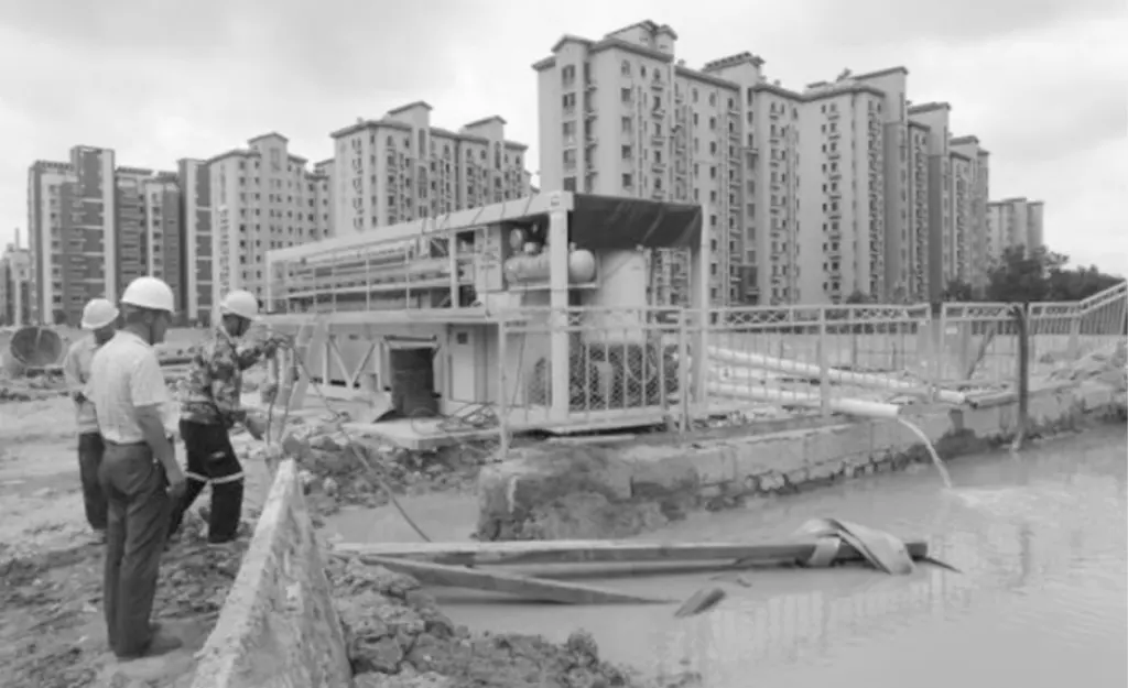
3.1 Application of the project The project is based on the sixth standard section of the construction of the first phase of the R2 railway line in Jinan (Figure 3). According to the data of field research, the project mainly adopts the technology of diaphragm wall construction, in which 200-300m3 of mud slurry is used in one trench (generally 400m3 in consideration of the surplus), and the mud slurry is generally recycled 4-6 times during the operation, and the mud slurry used in one trench is recycled to produce about 55m3 of waste mud slurry in the end, and there may be 3-4 trench construction at the same time in the later stage when the working surface is opened up completely. The equipment will carry out the mud slurry according to the construction time. The equipment will treat the slurry accordingly to the construction time.

According to the data calculation, the waste slurry treatment capacity is 55~220m3-1, and the treatment time is 24h. The average daily waste slurry treatment capacity is 140m3. According to the present situation, the application of this equipment is good, and it basically achieves a flow process of 2h after steady operation, and the slurry treatment capacity is 20m3 in each flow process, and the water content of discharged clean water and solid cake is about 35%. The water content of discharged water and solid cake after treatment is about 35%.
3.2 Factors Affecting Treatment Effectiveness
(1) Factors affecting cake thickness. According to the processing situation, it can be seen that the thickness of dry cake is positively proportional to the filtration time when the concentration of feed slurry is fixed, but the thickness of cake does not increase obviously when the filtration time reaches 45min.
(2) Factors affecting the water content of mud cake. The water content of the cake is related to the pressing pressure, the higher the pressing pressure is, the lower the water content is, at the same time, through the test, it can be determined that it is appropriate to control the pressing time at about 30min.
3.3 Optimisation of inlet design In practice, it is found that the inlet of the equipment is often clogged, so the inlet is optimised to solve the problem of clogging of the inlet in case of highly concentrated slurry.
3.4 Analysing and evaluating
3.4.1 Calculation of slurry handling capacity
(1) Single-cycle slurry treatment volume. The size of the slurry tank is 3m×6m, the liquid level of the single-cycle slurry tank is 40cm, and the single-cycle slurry treatment volume is about 7.2m3.
(2) Single-cycle water discharge. According to the flowmeter that comes with the slurry treatment equipment on site, it can be known that: the maximum water discharge is 10.9m3-h-1 when feeding, the minimum water discharge is 1.2m3-h-1, the feeding time is 1h, the feeding and draining time is about 50min; the maximum water discharge is 2.2m3-h-1, the minimum water discharge is 1.0m3-h-1, the pressing time is 30min, the pressing and draining time is 30min. The maximum water discharge during pressing is 2.2m3-h-1, the minimum water discharge is 1.0m3-h-1, the pressing time is 30min, and the press drainage time is 30min.
(3) Single-cycle mud cake discharge volume. According to the actual situation, the size of mud cake is 1m×1m, the average thickness of mud cake is 2.5cm, the number of mud cake discharged from one cycle is 59, and the volume of mud cake discharged from one cycle is 1.48m3.
3.4.2 Comparison of slurry treatment costs
(1) Cost calculation of adopting the mud transport method in the construction organisation design. According to the cost calculation of the project department, adopting professional tanker truck to transport and treat the waste slurry, one tanker truck can transport 25m3 of waste slurry, and the unit price of one truck is about RMB 2,000 per time, and the unit cost of treatment is RMB 80m-m-3.
(2) Costing of mud treatment with this equipment. After preliminary calculations, the use of new equipment for on-site waste mud treatment, equipment machine power of about 50kW, according to the efficiency of 7.2m3-h-1 treatment of waste mud, time about 2h, power consumption of 100 degrees, according to the industrial electricity tariffs, a work with electricity costs about 100 yuan. After separation of mud and water, the water can be directly recycled for on-site construction, and the dry mud can be transported by dump trucks, and the cost of dump trucks is 40 RMB-m-3, and the transport cost is 59.2 RMB. According to this calculation, the cost of adopting new equipment for waste slurry treatment is 22.1 RMB-m-3. In summary, the cost of using this equipment to treat 1m3 slurry is 57.9 RMB less than that of transporting.
4 Conclusion
(1) In this paper, field tests were carried out on loess slurries with specific gravity ranging from 1.08 to 1.32, and the slurries with specific gravity greater than 1.2 needed to be pre-treated with filter to remove large sand particles, otherwise the inlet would be easily clogged. After adopting the screen filter, the inlet was not clogged, but there was cake layering because the specific gravity of the slurry was different during the feeding process, which was solved by adding a stirring device to the filter.
(2) After the second pressing and backblowing technology, the water content of the cake is around 35%, and the specific gravity of the slurry is 1.08, so the compression ratio of the slurry treatment is around 9:1.
(3) The equipment designed in this paper covers an area of about 25m2, it is necessary to do a good job in advance of the site hardening, for the mud pool is small and more dispersed, can consider the equipment for miniaturisation of the design, so as to reduce the cost of a single piece of equipment, and more convenient for the transfer of the site.
Disclaimer: The copyright of this article belongs to the original author and the original source. Welcome to call us for consultation, technical exchanges, and material experiments.
Technical Consultancy: 188517-18517
 Plate and frame chamber diaphragm filter presses


